Induction-Resistance Heat Tracing System

Description
The system is used for freezing protection or maintaining material temperature in pipelines over 1,500 m long, enabling tracing pipelines of up to 30 km without a parallel supply line. The heating element consists of a 20-60 mm OD ferromagnetic steel tube with a wall thickness of min. 3.0 mm accommodating an insulated copper wire with a 10 - 50 mm2 cross section.
The conductor is electrically connected to the tube at the end of the leg, while alternating current is introduced between the tube and the conductor at the beginning of the leg. AC voltage is calculated based on the heat output requirement and the heat traced pipework length. The skin effect conductor is powered by a power board installed in a КТП М type packaged transformer substation.
Design
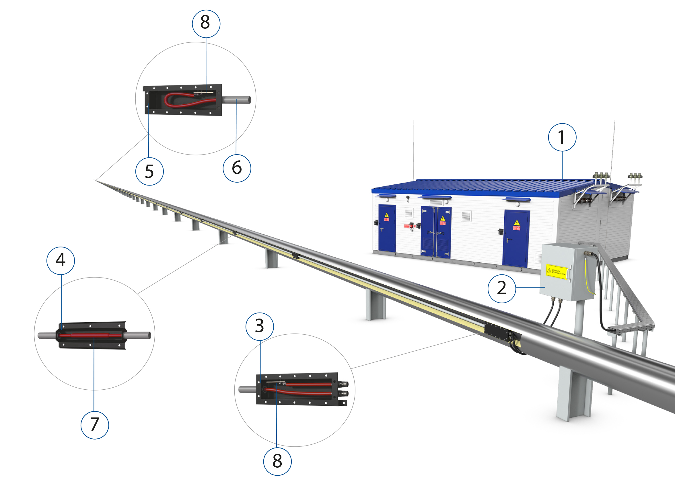
1. Packaged modular transformer substation
2. Power inlet box
3. Entry box
4. Pull box / junction box
5. End box
6. Steel heat tube
7. Skin conductor8. Earth bar
P.O. Details
Induction-resistance heat tracing systems are fabricated based on data sheets and specifications. A packaged transformer substation is supplied under a separate purchase order.
General Characteristics
|
Max exposure temperature |
260°С |
|
Max maintenance temperature |
200°С |
|
Supply voltage |
up to 230 V |
|
Conductor material |
Cu |
|
Specific power |
up to 165 W/m |
|
Hazardous area classification |
Hazardous, normal |
|
Certificate, Ex protection |
Pursuant to CU TR 012/2011, # ЕАЭС RU C-RU.МЮ62.В.01422/19, 1Ex e IIC T6...T2 Gb X |